Automotive Valvetrain
Introduction to the engine valvetrain
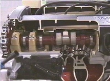
The valve train refers to the assembly of components designed to open and close the intake and exhaust valves. Most new engines have overhead cam assemblies like the one shown. Other designs locate the camshaft lower in the engine and use push rods to move valve assemblies. The camshaft is rotated by a timing belt, timing chain or direct gear.
Camshaft:
The camshaft (1) is manufactured with precisely machined lobes (2) which control valve opening. The number of lobes on a shaft is determined by the number of valves the shaft controls. Some engines use one shaft to control both intake and exhaust valves. Others have dedicated camshafts for each valve type. Engines designed with four valves per cylinder are normally equipped with dual camshafts for each row of cylinders.
Cam Lobe:
Cam lobes (2) are precisely machined into shapes which determine when the valve opens in relation to piston position, how far the valve is displaced, and the length of time the valve remains open. The distance between the end point of the base radius and the nose controls valve displacement. The geometry of the sides (flank) and nose determine how long the valve remains open.
Cam Follower:
The cam follower (3) is seated on top of the valve stem and spring (4) and is the surface upon which the cam lobe pushes to open the valve. The follower slides up and down within a bore machined in the cylinder head.
Camshaft Lift:
Camshaft lift is the distance between the end point of the lobe's base radius and the nose. The lift determines how far the valve will be displaced. Increasing the lift increases valve displacement.
Camshaft Duration:
Camshaft duration is the length of time the valve remains open. The geometry of the lobe's nose and flank determines the duration. A steeply angled flank results in a sharper nose. This produces a shorter duration.
Push Rod:
Engines designed with the camshaft located in the engine block use push rods (2), acting on rocker arms (3), to open valves. Push rods are seated on valve lifters (1) or tappets which ride on the camshaft lobes. Three types of lifters are used: hydraulic valve lifter, mechanical lifter, and roller lifter. Some push rods are hollow, providing a means to feed oil from the lifters to the rocker arms. This reduces wear on the push rod tip and rocker arm.
Hydraulic Lifters:
Hydraulic lifters are used most often since they can reduce valve train noise by maintaining zero valve clearance (no spacing between valve train components.) The oil filled lifters adjust automatically for changes brought on by temperature variations and wear of parts. Engine motor oil fills the inside of the lifter, pushing the lifter plunger up until all the play in the valve train is removed.
Mechanical Lifters:
Mechanical lifters, also called solid lifters, simply transfer cam lobe action to the push rod. They do not contain oil and are not self adjusting. As a result, they require periodic adjusting. Valve trains using mechanical lifters are prone to a clicking or clattering noise as the valves open and close. This is why hydraulic lifters are more common.
Roller Lifters:
Roller lifters are either mechanical or hydraulic. Designed into the lifter is a roller that rides the cam lobe, reducing friction between the camshaft and lifter. Friction between these two components is one of the highest friction points in an engine.
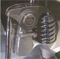
Spring Retainer:
The spring retainer is designed to hold in place the valve stem tip. This allows the rocker arm to act directly on the valve.
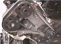
Timing Chain:
Timing chains are becoming the standard for turning both the intake and exhaust camshafts. The chains are located on the engine's front end, and are pulled by a drive sprocket (1), which is turned by the engine's crankshaft. Timing chains are required for both the intake cam sprocket (2) and the exhaust cam sprocket (3). A chain guide (4) is also provided. Some engines still use belts instead of chains. In either case, excess slack or play will degrade engine performance.
Timing Belt:
A timing belt instead of a timing chain may be used to turn the camshafts. The inner side of the belt is designed with square (cogged) teeth which prevent the belt from slipping. The belt should be checked periodically for wear and proper tension.
Belt Tensioner:
The belt tensioner is a spring-loaded wheel which keeps the timing belt in tension and aligned with the cam sprocket. The smooth side of the timing belt rides over the tensioner. The tensioner applies a force on the backside of the belt. This keeps the belt in tension. Whenever the belt needs to be removed, the tensioner can be pulled away, freeing the belt.
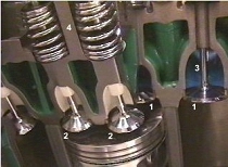
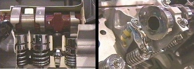
Valves:
Each cylinder has at least one intake valve (1) and one exhaust valve (2). Some engines are designed with two sets of valves per cylinder as shown in the photo. The intake valve has a larger diameter than the exhaust valve, which maximizes air flow to the cylinder. The exhaust valve must withstand higher temperatures than the intake valve since the air flowing past the intake valve keeps the intake valve at a lower temperature. However, both intake and exhaust valves must transfer their heat to the cylinder head otherwise they will burn.
Valve Springs:
Valve springs (4) provide a resisting force that returns displaced valves to their closed position. The spring may be a one-coil design or a two-coil design which has inner and outer coils. The second coil increases the amount of force holding the valve closed.
Sodium Filled Valves:
Sodium filled valves are used when extra cooling is required. The hollow valves contain sodium which melts during engine operation. Valve action causes the sodium to circulate, removing heat from the valve head. The heat travels up the valve stem (3) and is transferred to the cylinder head. Coolant channels in the cylinder head (shown in green) carry the heat away.
Stellite Valves:
Stellite valves have a hard metal coating that prolongs valve life. Back in the days of leaded gasoline, the lead additives coated the valves, providing added protection. With unleaded fuels now being burned, the hard metal coating does the protecting.